 Gusset
Everything Gusset does
Stress, deflection and factor of safety on the solid model you already have, with every weld and bolt checked when you want them, and a verdict on how far to trust the answer.
The geometry is the model
Gusset lays cells over each part and works out which bit of each cell is metal. Thin walls, small holes and awkward fillets do not need cleaning up first, and a frame of hollow sections with plates welded to it is one model, not a beam model and a shell model stitched together.
- Each part gets cells lined up with it and stretched along its walls
- Adaptive passes refine at welds, loads and supports
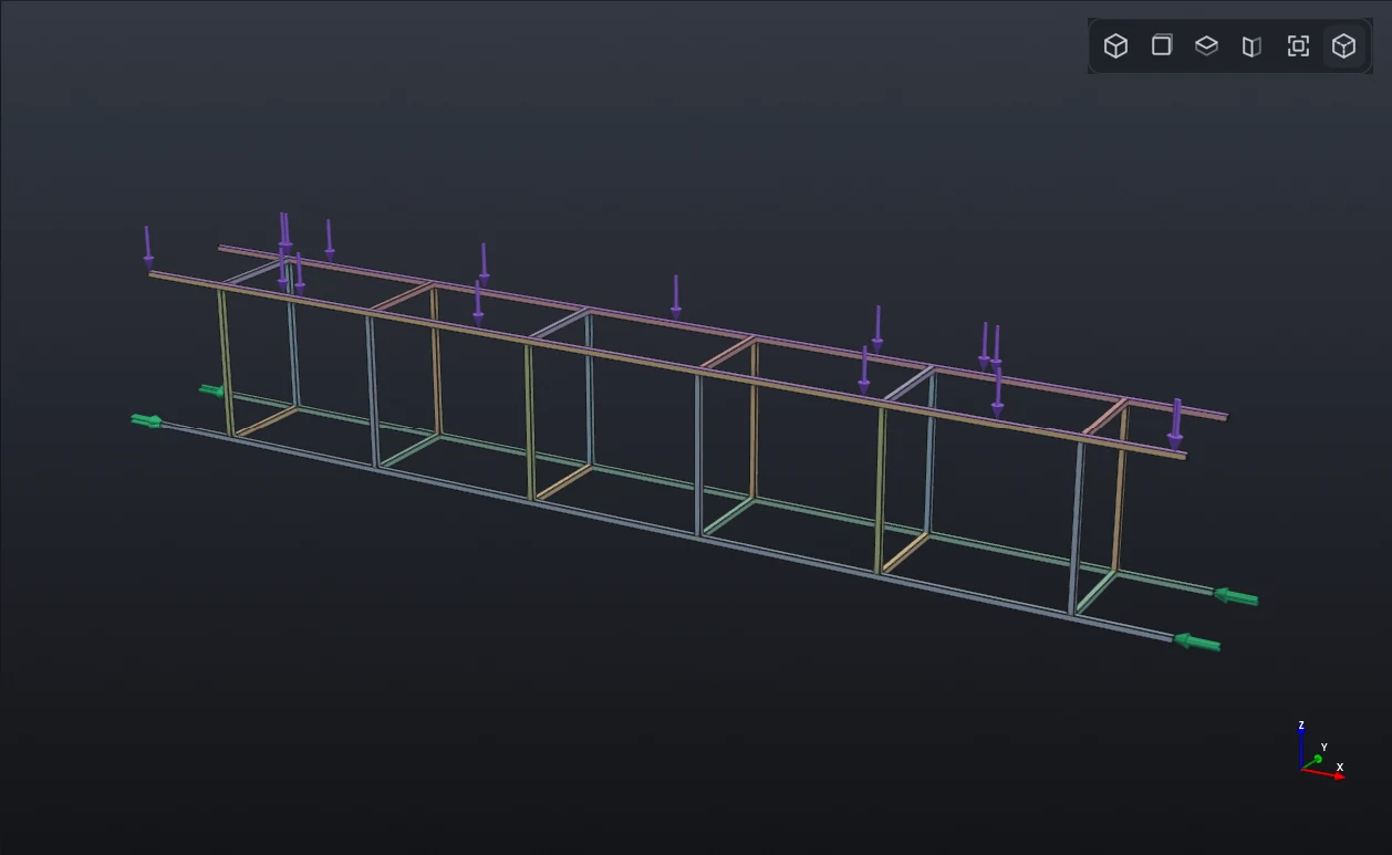
- This one is ten metres of 50 mm tube with a 2 mm wall, 28 members
Every weld and bolt, checked
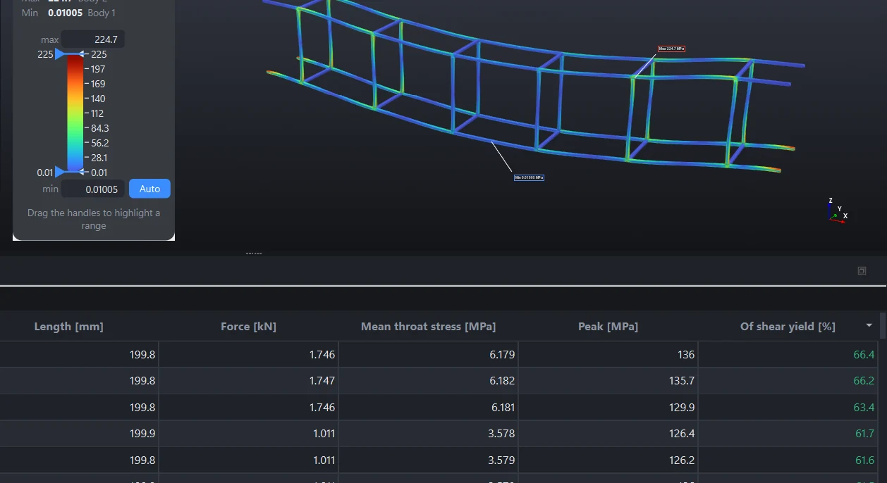
Parts start bonded where they touch. Tick one box and the welds are laid out as a fabricator would lay them, a fillet round the edge of the touching face sized from the thinner part, and bolts are found in the holes that line up. You can set any of them yourself.
- Force through each weld and its throat stress against the parent metal's shear yield
- Bolts found from holes: tension against proof load, shear, and whether the joint would slip
- Stitch welds, butt welds, your own leg sizes
- A weld guide for the fabricator, as a PDF
It tells you when not to trust it
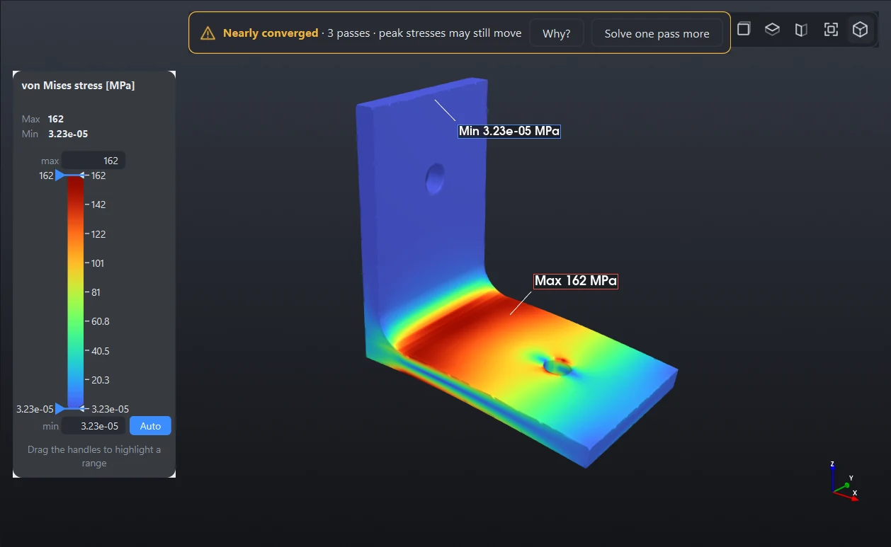
A model that is too coarse is too stiff, and its stresses come out low. Most programs leave you to find that out. Gusset says so over the results.
- Converged, nearly converged or not converged, with the reasons
- Judged on the change in stress between passes, not only energy
- Peaks at weld roots flagged as singular, not reported as real
- One click to solve a pass more
Something to hand over
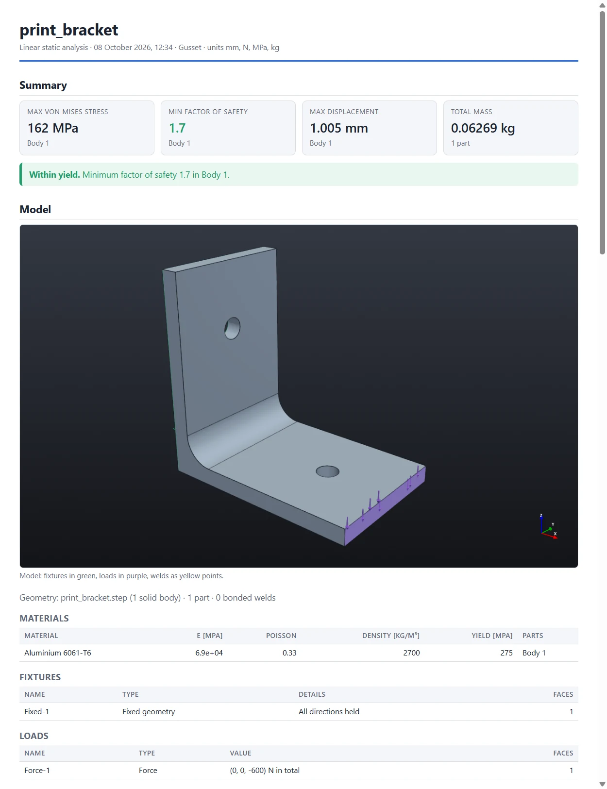
One click writes the report as a web page or PDF: the model, what holds and loads it, materials, plots, the table of parts, welds and bolts, the convergence history and every note the solver made.
- Factor of safety against yield for every part
- Probe values at the points you clicked
- Animations of the loading as GIF or MP4
Held the way it is really held
A support that is too stiff hides the stress you are looking for. Choose how each face is held, and see what each support carries.
- Fixed, roller, pin in a hole, anchor bolt, a set displacement
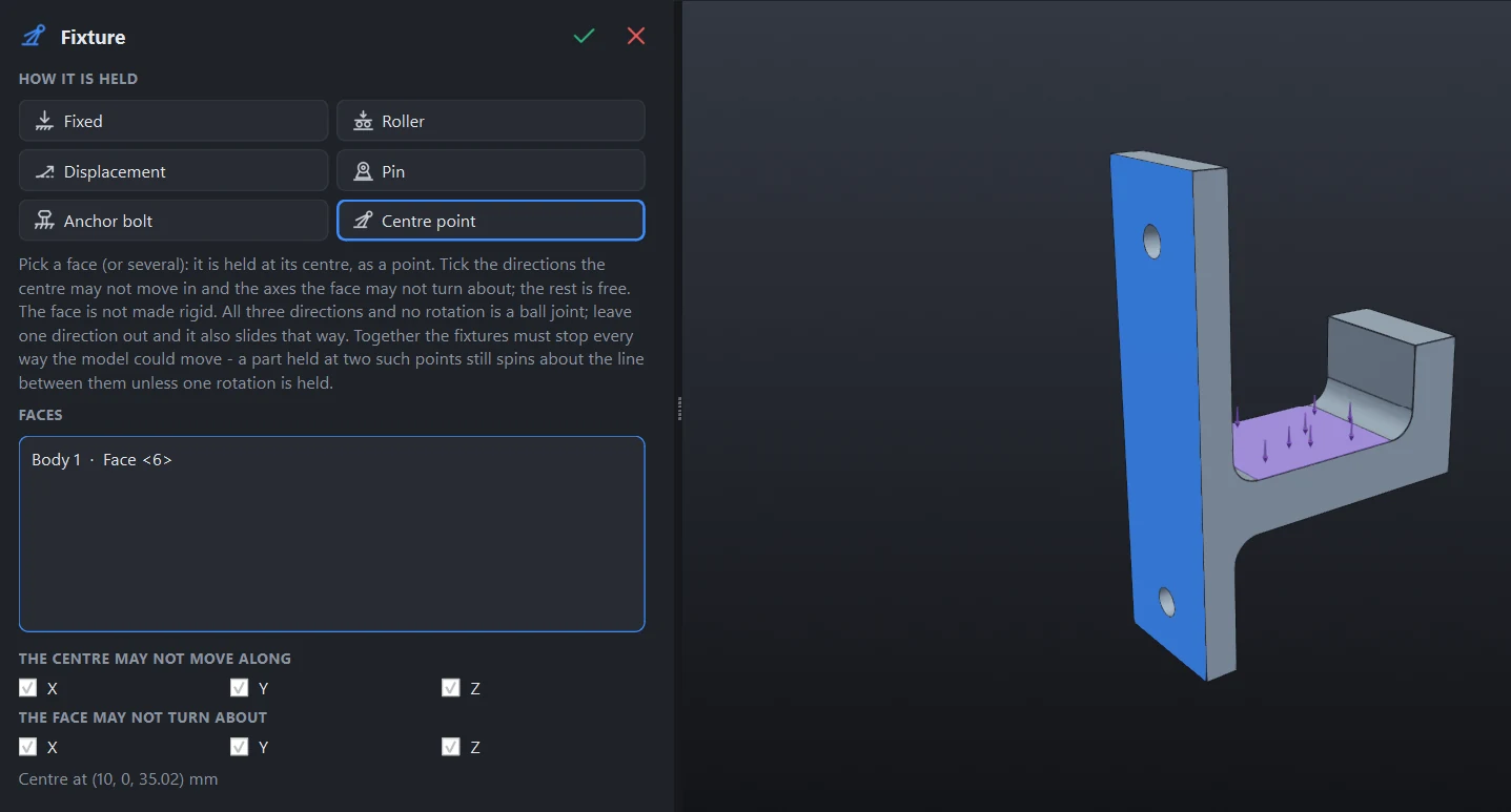
- A face held at its centre as a point: a ball joint, or one free to slide
- The reaction at every support, balanced against the loads
- Change the CAD, open the new file, and the supports and loads follow it
Which way up should you print it?
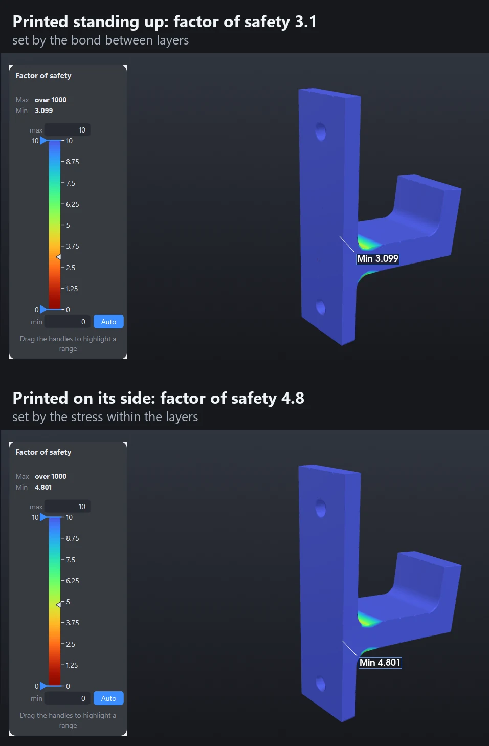
A print is weaker between its layers than within them. Say which way the layers are stacked and the factor of safety checks the bond between them as well.
- The same hook, the same 150 N: 3.1 printed standing up, 4.8 printed on its side
- Stress across the layers and shear between them as plots of their own
- PLA, PETG, ABS and nylon built in; put in your own measured values
What is in the box
Linear static stress
von Mises and principal stress, displacement, factor of safety. Steel, stainless, aluminium, titanium and cast iron built in; add your own.
3D-printed parts
A print is weaker across its layers than within them. Set the build direction on each part and the factor of safety checks the bond between layers as well. PLA, PETG, ABS and nylon built in; plywood and carbon fibre sheet are there to try, marked experimental, with finer cells put round their holes.
Buckling and natural frequencies
Buckling load factors for slender frames and columns, and the frequencies a structure vibrates at as it is held, each with its mode shape. Keep a frame clear of the motor that sits on it.
Real supports
Fixed and sliding faces, pins free to turn, anchor bolts with washers, a face held at its centre as a ball joint, prescribed displacements.
Real loads
Forces, pressure, a force and moment at a remote point, hung masses, self-weight in any direction.
Joints three ways
Bonded, for the parts themselves. Welds laid out and checked at the throat. Bolts, quick for the pull and shear at each one, or with contact and preload for where the joint opens.
Made to be read
Min and max pointed out on the model, a legend you can drag to show only what is above a limit, mouse controls set up like the CAD you use.
Reactions at the supports
The force and moment each fixture holds, balanced against the loads and own weight, so you can see that each support carries what the real one would.
Change it and solve again
Open a changed version of the model and the materials, supports and loads follow it. Change only a load and the last solution is reused, so the answer is back in a fraction of the time.
What it is not
Gusset does linear static analysis, linear buckling and natural frequencies. It does not do plasticity, large deflections, fatigue, the response to a load that varies in time, impact or heat. It runs on Windows. It is a tool for an engineer's judgement and does not replace it.
Your models stay with you
Everything is solved on your own computer. No model, load or result is uploaded. The account holds your e-mail address and which licence you have, and that is all.
How to use each of these is in the documentation.
Try it on your own frame
The free Hobby licence is the whole program. Open a STEP file and see the answer.